
Davidson’s Telescopic Rifle Scope
David Davidson’s patent and drawings · Originally published January-February 2023 · pp. 43–46
David Davidson was a sports enthusiast and a soldier. He had a lengthy life, living from 1811 to 1900. Davidson served as a cadet and then an officer from 1827, when he was sixteen, until 1848, when he retired after twenty years of service in the Bombay Army of the Honourable East India Company. The HEIC governed sizable portions of the Indian subcontinent on behalf of indigenous princes and the British Crown, In addition to his military responsibilities, he had a deep interest in hunting activities and firearms technology. When Davidson was serving as a lieutenant with his army company at Fort Asseergurh in 1832, he installed a telescopic sight on a gun for the first time. The military adjutant sold him a single-barreled, flintlock rifle. He added a straightforward draw telescope to the barrel. It was built by Swiss-born gunmaker Samuel Staudenmeyer of Cockspur Street in London. The caliber and the way the telescope was secured are the only other details known about this first item. In 1839, Davidson was appointed a revenue surveyor at Nassik while still serving as an officer in the Bombay Army. He had more time now to practice using the telescopic sight, go big game hunting, and make improvements. In that year, Davidson requested a heavy-barreled, small-bore percussion rifle with a telescopic sight from the still-famous gunmaker James Purdey of 314 ½ Oxford Street, London. It should be noted that at the time, “small-bore” referred to a barrel that fired a lead ball weighing half an ounce. A belted round ball was discharged by Purdey’s two-groove rifling, then thought to be the best at the time and for many years following. The price of a Purdey double gun was three times his average yearly pay of 90 guineas ($470). Davidson was not happy with the telescope installation when his gun arrived in India, so he had it changed and upgraded. As his preferred sports weapon, Davidson had Purdey create a 10-inch double-barreled percussion pistol with a skeleton stock and telescopic sight. He used it to kill antelope at distances of 100 and 200 yards, demonstrating his prowess as a rifleman and hunter more so than the accuracy of the rifled pistol and its sight. In the 1830s, he also equipped an air-cane with a telescopic sight. The aircane was shaped like a walking cane but it had a small-bore rifle barrel that fit inside a larger smooth-bored barrel in the stem, but could be removed. The grip end contained a high-pressure cylindrical air reservoir and a tiny valve cocked with a key and fired by a pop-out trigger. It fired harpoons for fish, shot for birds, and ball for game. Davidson employed this to kill cobras and other snakes. When at sea in the 1840s, he used a singlebarreled, rifled percussion pistol equipped with “a minute telescope” to fire at a shark. It is important to take note of Davidson’s further work on sporting weapons and ordnance. He had a piece written about his trials with elongated rifle rounds instead of the then-standard spherical ball published in the Bombay Sporting Magazine in 1833. He perfected a lead bullet with a pointed nose, a circular base, and a cannelure or flute around the center that demonstrated a significant improvement in accuracy and range. Sportsmen in Scotland and India frequently employed Davidson’s cannelured bullet, begging him and his gunsmith in Edinburgh, Scotland, to obtain moulds for custom casting. This was well before a similar bullet was adopted for military rifled arms fifteen years later. Davidson also conducted research on projectiles for use in heavier weaponry. Professor William Piazzi Smyth, the astronomer-royal for
David Davidson. Scotland in 1839, presented his paper, Rifled Cannon, to the Royal Society in Edinburgh. In order to increase range and accuracy, Davidson recommended rifling the common bronze and iron muzzle-loading field cannon with four deep grooves and utilizing long iron bolts and shells equipped with copper flanges to engage the rifling. Before the army and navy would use this idea, another twenty years would pass. It was the telescopic sight that brought Davidson distinction. Before he was able to patent his Military Telescopic Sight in 1862, he spent more than thirty years perfecting the sight and, importantly, its mounting. Throughout his time with the East India Company, sportsmen in India were hunting both large and small game. Lieutenant Isaac Shannon was a sniper, one of five in a “company of special sharpshooters” serving in General Benjamin Franklin Cheatham’s Division under Lieutenant John M. Ozanne. Shannon wrote C. Frederick Lowe, an English sporting rifleman, a letter containing information about Whitworth rifles and their distribution. Five of the telescopic-sighted rifles were given to each division’s top marksmen in the Confederate Army of Tennessee. A sniper company, in General Patrick Cleburne’s Division, was said to have carried 30 Whitworth rifles and 16 Kerr rifles. Several of Cleburne’s sharpshooters have been identified.
Davidson’s patent describes his telescopic sight: “A.D. 1862, 19th DECEMBER. No 3399 Telescopes for Fire-arms.
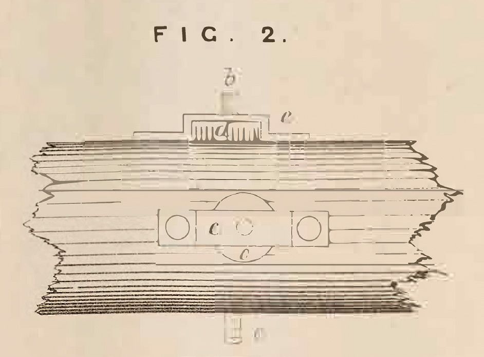
LETTERS PATENT to David Davidson, of Woodcroft, Morningside, near Edinburgh, North Britain, Retired Major in the Indian Service, for the Invention of “IMPROVEMENTS IN THE CONSTRUCTION OF TELESCOPES, AND IN THE METHOD OF ARRANGING AND FIXING THE SAME IN COMBINATION WITH FIRE-ARMs, FOR THE PURPOSE OF ADJUSTING THE AIM THEREOF,” Sealed the 16th June 1863, and dated the 19th December 1862. PROVISIONAL SPECIFICATION left by the said David Davidson at the Office of the Commissioners of Patents, with his Petition, on the 19th December 1862. I, DAVID DAVIDSON, of Woodcroft, Morningside, near Edinburgh, North Britain, Retired Major in the Indian Service, do hereby declare the nature of the said Invention for “IMPROVEMENTS IN THE CONSTRUCTION OF TELESCOPES, AND IN THE METHOD OF ARRANGING AND FIXING THE SAME IN COMBINATION WITH FIREARMS, FOR THE PURPOSE OF ADJUSTING THE AIM THEREOF,” to be as follows:— This Invention consists partly of the following improvements in the construction of telescopes to be used in combination with fire-arms. The field bar of the telescope is furnished with two slides moving at right angles to each other, and worked by screws, each slide carrying a cross hair, one of such hairs thus being horizontal, while the other is vertical. The horizontal hair is for minute adjustment of the telescope in elevation, the vertical hair being for allowance for side wind. The intersection of the lines when adjusted gives the aim. This improvement is applicable to the telescope, whether the latter is fixed to the rifle or other piece in the manner herein-after described, or in any other manner. Another part of this Invention consists of improvements in arranging and fixing telescopes in combination with firearms, and is especially applicable to rifles and other small arms. The telescope is applied at the side of the piece, so that when depressed for the long range it clears the muzzle of the barrel. The body of the telescope is enclosed in a metallic tube, on which are fixed two collars, one at the object end of the telescope, and the other about five inches from the eye-piece. The collar next the eye-piece is constructed with a neck furnished with projecting cams or lugs, the said neck entering into a corresponding hole or groove in the shield plate of one of the lock screws. A joint is thus formed, in which a sufficient amount of elevation and depression can be given to the telescope. The collar at the object end of the telescope is furnished with a quadrant, which latter presses against a plate of metal inserted into the stock about ten inches, or at some other convenient distance from the breech. A screw furnished with a milled bead passes through the before-mentioned plate of metal, by which the quadrant can be set and clamped at any required angle… …NOW KNOW YE, that I, the said David Davidson, do hereby declare the nature of my said Invention, and in what manner the same is to be performed, to be particularly described and ascertained in and by the following statement, reference being had to the Drawings hereunto annexed, and to the figures and letters marked thereon (that is to say):— My said Invention consists of certain improvements in the construction of telescopes, and in the arrangement thereof in combination with fire-arms, and supplies the requirements in the method of taking aim, consequent upon the improvements which have recently been made in the construction of the rifle, and the great extension of its range. One part of my said Invention consists of the following improvements in the construction of telescopes to be used in combination with fire-arms, as before mentioned :— The field bar of the telescope is furnished with two slides moving at right angles to each other, and worked by screws, each slide carrying a cross hair or line, one of such lines thus being horizontal, while the other is vertical. The horizontal line is for minute adjustment of the telescope in elevation, the vertical line being for allowance for side wind. The intersection of the lines when adjusted gives the aim. This improvement is applicable to the telescope, whether the latter be fixed to the rifle or other piece in the manner herein-after described, or in any other manner. This portion of my said Invention will, however, be more clearly understood by reference to the annexed Drawings. Figure 1 is a cross section of the field bar (somewhat enlarged) at the focal point, shewing the vertical slide carrying the horizontal line. The slide a has a fine screw b at its upper end, and a square pin c at its lower end. This slide is dropped into the groove in the field bar made to receive it, through a slot cut in the tube of the telescope. It is worked into position by means of a milled nut d, which nut is kept in its place by a strap e held to the tube by screws. When the milled nut is turned, the horizontal line is raised or depressed for the different elevations which are marked on the square pin C projecting through the lower side of the tube. The slide for the vertical line is exactly similar to that for the horizontal one, but set at right angles to it. The moving of the vertical line by the last-mentioned slide gives the required correction for side wind. Figure 2 is a side view of the part of the tube of the telescope where the lastdescribed arrangement is made. I will now proceed to describe the other part of my said Invention, which consists of improvements in arranging and fixing telescopes of whatever kind in combination with firearms, and is especially applicable to rifles and other small arms. The telescope is applied at the side of the piece, so that when depressed for the long range it clears the muzzle of the barrel, The body of the telescope is enclosed in a metallic tube, on which are fixed two collars, one at the object end of the telescope, and the other about-five inches from the eye end thereof. The collar next the eye end is constructed with a neck furnished with square projections or lugs, the said neck entering a corresponding hole in the escutcheon plate of one of the lock screws, the lugs taking hold of the inside of the plate on the collar being twisted. A joint is thus formed in which sufficient amount of elevation or depression can be given to the telescope. The collar at the object end of the telescope is furnished with a quadrant, which latter presses against a plate of metal inserted into the stock of the piece at about ten inches, or at some other convenient distance from the breech. A screw furnished with a milled head passes through the stock under the barrel, and through the beforementioned plate of metal, and by means of a milled nut on the end of this screw (the head of which screw takes hold of the edge of the quadrant) the quadrant can be clamped securely at any required angle. These arrangements will be more clearly understood by reference to the annexed Drawings. Figures 3, 4, and 5, are views of the front collar with quadrant 1 ; Figure 3 is a front view, Figure 4 a side view, and Figure 5 an oblique view in perspective; Figures 6 and 7 are front and side views of the collar near the eye end of the telescope, shewing the neck G and projecting edges m, m; Figure 8 is a view of the telescope with the collars attached. The eye-piece pulls out to focus, and is furnished with an india-rubber shield or buffer to prevent injury to the eye. Figure 9 is a view of the part of the rifle to which the telescope is fixed. To fix the telescope it is necessary to hold it at right angles to the piece with the object end uppermost, and in this position to enter the neck g of the collar at the eye end into the hole f of the screw escutcheon plate. The telescope is then twisted a quarter of a circle, so as to bring the quadrant i (on the other collar) to press upon the plate h into the stock. When so twisted, the lugs m, m, on the neck of the collar at the eye end take hold of the inner face of the escutcheon plate, (see Figure 11, shewing a cross section of the stock at this point,) and draw the telescope tight to the piece, while the edge of the quadrant at the other end is seised by the overlapping head k (Figures 9 and 3) of the clamping screw l, shewn in cross section in Figure 10. On the flat head k of this clamping screw (which is flush with the upper ledge of the quadrant) is a fine line or arrow. When the zero of the quadrant is brought to correspond with this line, the axis of the telescope is by construction exactly parallel to the axis of the barrel of the piece, both in the horizontal and vertical plane, and the telescope may be securely fixed in this position by a turn of the milled nut n, Figure 10, at the end of the damping screw l. This zero of the quadrant is for aim at point blank, or before the bullet begins sensibly to drop. To give elevation at the longer distances, the clamping screw is undamped, and the object end of the telescope is depressed, until the division on the quadrant marking the the cross line in the field of the telescope is moved up or down, as the case may require by the milled nut d, Figure 1. Again, should the shot from the influence of the wind strike to either side or the mark, correction is given by means of the other milled nut o, Figure 1, working the horizontal line, as already described. In Figure 9 the telescope is represented attached to the rifle, and fixed for the One thousand yards range. I should observe that the telescope admits or being used without the arrangement, by which the outer tube is made to move up and down for the different elevations. For example, if I use a telescope of small power and large field, and fixed to the side of the piece in any secure manner, so as to clear the muzzle when looking through it at the object, I obtain sufficient scope for giving any amount of elevation up to a very considerable range without depressing the telescope itself, but by simply raising or depressing the cross lines within the telescope, the amount for the various ranges being marked on the square pin c at the end of the slide a, Figure 1. The advantages of this Invention may be briefly stated as follows :— 1. By means of the telescope, constructed and arranged as herein-before described, error of aim is, practically speaking, annihilated. 2. It enables a rifleman to search out and aim at an object which cannot be detected by the naked eye.
elevation for the particular distance required comes exactly to coincide with the arrow on the head of the clamping screw, and then the quadrant is clamped, and the rifle is ready for use at that distance. If, after a trial shot, it is found that a little elevation more or less is required (instead of attempting to make the correction by moving the quadrant),
- While on the piece it does not interfere with the use of the ordinary sight, and it can be taken off or put on in a moment. 4. In aiming at long ranges, instead of having to raise the eye and lift the cheek from the stock, as with the ordinary sights, the cheek continues to press the stock, and the eye is very slightly raised.