
Dr. Edward Manyard – Surgeon Dentist and Inventor
By Peter H. Jacobsohn, D.D.S. · Originally published September-October 2022 · pp. 3–18
Historical Publications LLC Military Antique Collector 520 Folly Road, Suite 25 PMB 379 Charleston, SC 29412 800-777-1862 Email: [email protected] Website: MilitaryAntiqueCollector.com
mind and exceptional mechanical skills, led him to make significant contributions in both fields. Maynard is primarily known for innovation in the field of small arms. In 1845 Maynard patented a tape priming system for small arms that was intended to replace the percussion cap system adopted by the U.S. Army in 1842. The percussion cap was a major improvement over flintlock gun ignition that had been the standard since about 1640. However, there was still room for improvement. The percussion cap was a small brass cap filled with mercury fulminate. It was placed on a hollow cone mounted to the gun barrel. The fulminate would ignite when struck by the gun‘s hammer. The resulting flame would, in turn, pass through the cone into the barrel to ignite the powder charge. It could be quite awkward, depending on conditions, to have to place caps on the cone each time the gun was fired. Maynard’s priming system was designed to eliminate dealing with individual percussion caps and thereby increase the rate of the weapon’s firing. His system, known as the Maynard Tape Primer System, involved connecting a series of regularly spaced self-contained percussion primers in a varnish coated waterproof tape, or roll, similar to those used in the toy cap guns of our youth. The primers were small pellets containing fulminate of mercury. The concept of using a pellet may have been inspired by his dental practice. The dental restorative amalgam in use at the time could be provided in pellet form. The tape length varied and could include approximately 20-50 primer pellets. The roll of tape and its primer pellets were used in the Maynard Primer Lock System. The lock consisted of a hammer and a self-contained magazine compartment that held the tape and its primers. An internal ratchet and pawl advanced the tape when the hammer was cocked. As the hammer was cocked, a primer pellet was pushed out of the magazine and over the gun’s cone, or nipple. The priming compound detonated when the hammer struck it. A sharp edge on the hammer cut off the used primer. The magazine compartment was sealed by a hinged cover. The entire system was designed to be incorporated into any type of firearm. On June 15, 1845, Dr. Maynard wrote to the U.S. Government’s Secretary of War, William Wilkins. He asked for an official trial of the lock and priming system which he had installed months
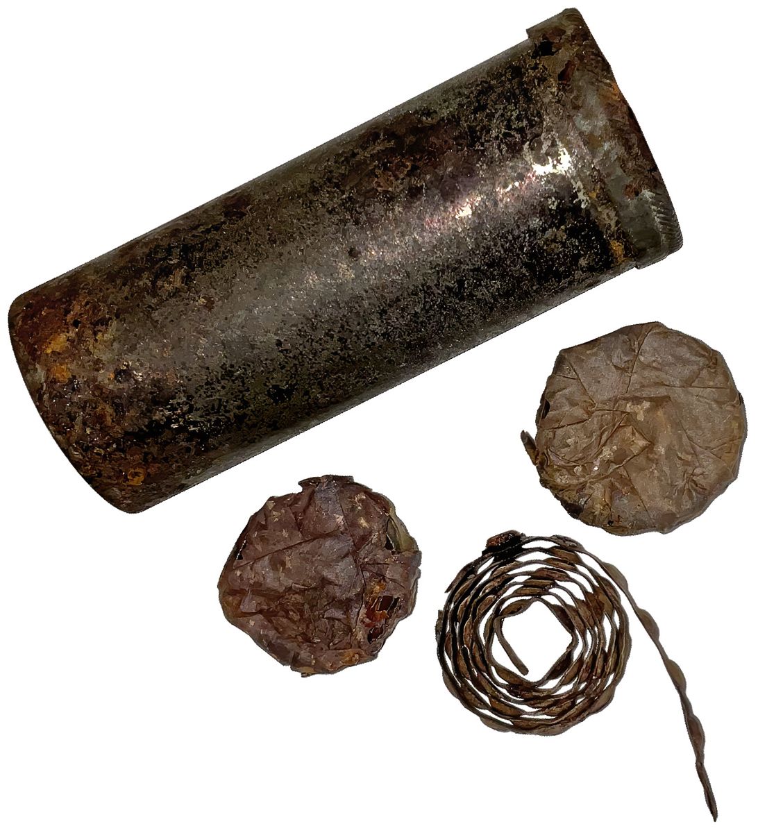
Maynard tape primer tin case with waterproof wrapped primer and an opened coil of primers.
earlier on a number of muskets. He wrote “Every principal upon which my invention rests is so simple, demonstratable and self-evident that the whole range of experiments can be made within a short time.” On January 21, 1845, Special Order No. 3 was issued by Assistant Adjutant General L. Thomas, Washington, D.C., to convene a board of Army and Navy officers to examine Dr. Maynard’s invention and report on its potential for adoption by the service. Extensive trials of Maynard’s device were conducted from January 29 to February 27, 1845. The trials chiefly consisted of firing exercises using a common percussion musket and muskets fitted with Maynard’s lock and using his primer. The results were compared, and the Maynard lock muskets excelled in virtually all tests. The joint Board of Army and Navy officers met on February 5 and agreed upon the following report which they approved, signed and forwarded to the Secretaries of the War and Navy Departments: “The joint Board of Army and Navy officers directed to examine a new percussion lock for small arms invented by Dr. Edward Maynard, have the honor to report that they assembled at Washington Arsenal on the 29th of January last, and after examining the subject submitted to them, have arrived at the following conclusion: “The Board is of the opinion that the principles on which this lock and its priming are constructed may be applied with great practical utility to firearms in general, and that they are applicable to small arms for the military and naval services; that the apparatus for this purpose is exceedingly ingenious, and accomplishes most of the objectives proposed by the inventor.” On March 13, 1845, Dr. Maynard made the following offer to the Government: “As a Board of Officers of the Army and Navy have reported favorably on my patent invention of an improved musket lock and percussion priming, I respectfully offer for the approbation of the Secretaries of War and the Navy to sell to the United States the right to make and use my percussion priming and lock for: 5000 muskets for $5,000 10,000 muskets for $7500 20,000 muskets for $10,000 100,000 muskets for $25,000” On March 20, 1845, Secretary of War, William Marcy, signed a contract with Dr. Maynard whereby Maynard would sell to the Government for $4,000 the right to apply his system to 4,000 muskets. On March 22, 1845, the Naval Bureau of Ordnance paid $1,000 for the right to apply the new device to a number of muskets not to exceed 1,000. Jefferson Davis became Secretary of War in 1853 as a member of the Franklin Pierce administration. After Davis assumed office, he contracted with Maynard in early 1854, for the sum of $50,000, the right of the government to use his design without restriction on Army and Navy small arms. In 1855 the Maynard Tape Primer System was installed on continued on page 13
E. MAYNARD. Priming-Cock. Patented Sept. 22, 1845. PERCUSSION-PRIMER AND GUN-LOCK THEREFOR. Specification of Letters Patent No. 4,208, dated September 22, 1845; Antedated March 22, 1845.
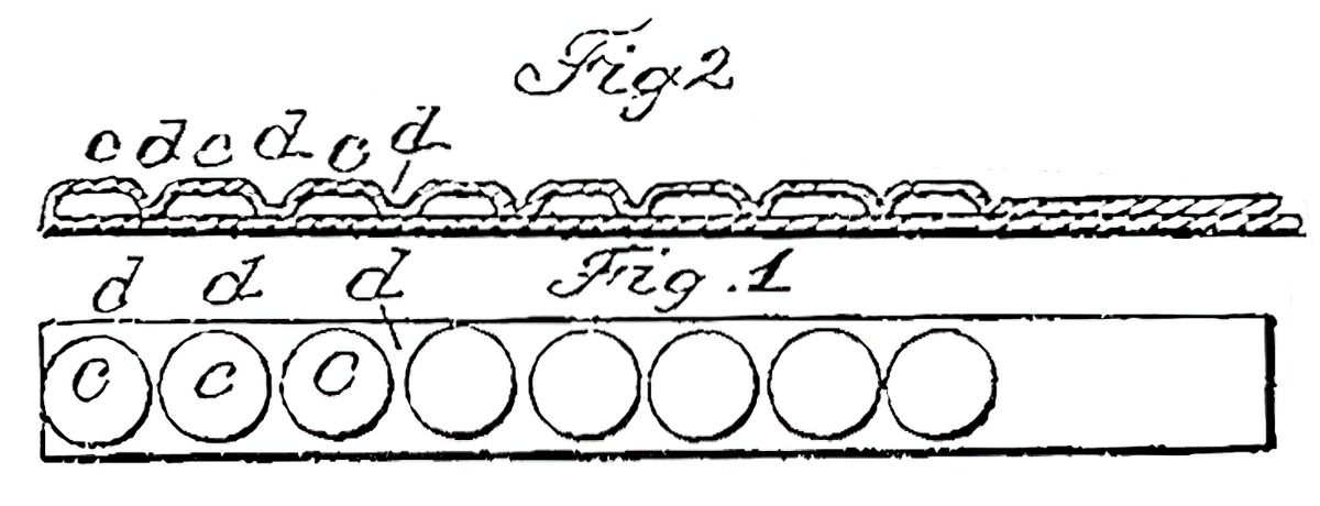
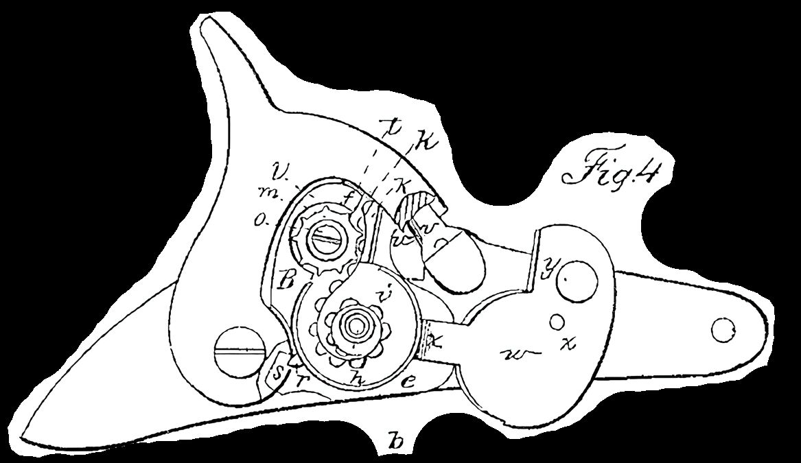
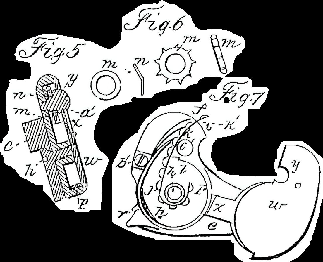
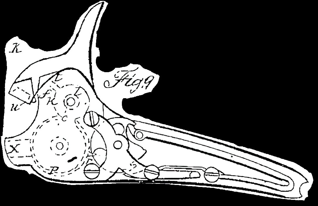
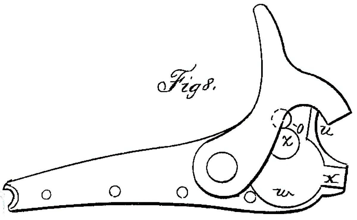
To all whom it may concern: Be it known that I, EDWARD MAYNARD, of the city of Washington, District of Columbia, have invented a new method of making, percussion-primers, connected together in a series, but having the fulminating or percussion matter of each primer separated from the others in the series, and also a method of applying the same to all kinds of firearms, and that the following is a full, clear, and exact description of the principle, manner of making, and modes of using the same. The nature of the first part of my invention consists in so making primers of fulminating mixtures, or such compounds as ignite by percussion, as to have a series of any number of primers in a continuous strip, but each separated from the others, to prevent the communication of fire from the one exploded to the others, by means of which a magazine of such primers can be carried in connection with the gun, or other firearm, and each primer exploded without any danger of communicating the fire to the rest in the series. And, the second part of my invention consists, in connecting with all kinds of fire arms such as cannon, guns, pistols, &c., a magazine for containing primers made in accordance with the first part of my invention from which the primers, may or can be fed forward to the place where they are to be cut off preparatory to being exploded, or directly to the place of explosion, this magazine being so connected with the hammer or other moving part of the look as to push forward the primer by the movement of the lock. Having thus described the chief characteristics I will, to enable any one skilled in the art to make and use my invention, minutely describe its various parts, essential modifications, and manner of using the same, making reference to the accompanying drawings that make part of this specification, in which— Figure 1, is a plan of the series of primers, Fig. 2, a longitudinal section of the same showing one manner of making them with the separations between the primers, Fig. 3, an outside representation of the flint lock altered to receive my improved magazine and primers, Fig. 4, the same with the magazine opened to show the location of the series of primers, and the manner of feeding by means of the cock or hammer. Fig. 5, a transverse section of the same taken at the line A—B, of Fig. 4. Fig. 6, a plan and section of the wheel of cogs which moves forward the primers, and a spring washer placed under it. Fig. 7, a modification of the magazine in which the primers are moved forward without the wheel. And Figs. 8, 9 and 10 outside, inside and top views of a back action lock in which the magazine is let into the lock plate and the primers moved out by means of the tumbler.
In all these figures the same letters indicate corresponding parts. The mode of making the series of primers, under the first part of my invention, which I prefer, is that represented in the accompanying drawings, and is as follows, viz: A strip of paper, either in a moist or dry state is, by means of appropriate instruments and by the application of pressure, forced out into cup forms, as at c, c, c, the spaces d, between the cups being sufficient to prevent the communication of fire from one to the other. These cups are filled with the percussion or fulminating mixture, even with the original surface of the strip, it is then coated with a varnish of gum lack dissolved in alcohol, and covered with a thin strip of paper, and the whole is then varnished over, which renders it imperviable to moisture. It is important that the two strips of paper be made to adhere in the spaces between the several cups containing the fulminating compound, and that none of the mixture be deposited or left on the spaces or divisions. The method which I have pursued in making these primers is to form the cups, in the paper by forcing in the mixture, the one operation being sufficient instead of two, and it will be evident that this can be done by placing the strip of paper on a bed, having a counter sink of the form intended to be given to the cup and laying the paper thereon, and the mixture
on a strip of paper or other substance by glue or other mastic and the whole coated with varnish. Or the primers may be separated from each other by some incombustible substance. Or the mixture may be put in a soft metal tube, and the separation be formed by flattening the tube at proper intervals to interpose between each two primers the contact of the inner surface of the tube. In short the principle of making primers in a connected strip and each separated from the others may be applied in a variety of ways and yet retain this essential character which renders it more safe and convenient than any other mode of making primers, with which I am acquainted. And although I deem it important that the separation between the primers be a depression, as affording facilities in feeding or moving them out preparatory to explosion as will be fully explained hereafter, yet the great end of safety against communicating fire from one to another of the series, and protection against moisture fully attained. Under the second part of my invention, as indicated above, the primers are coiled, and put in a magazine e, and pushed through an aperture f, to be cut off by a cutter on the hammer preparatory to explosion. In Figs. 3, 4 and 5 this magazine is represented as applied to the common flint lock, which, when thus altered, I denominate the magazine percussion lock. The magazine is represented as attached to the lock plate by two screws, g, and h, in manner
forced into it by a piston working in a hole in a plate placed above the paper to keep it in place and to hold the mixture, and form a guide for the piston. The fulminating mixture which I employ is composed of 100 parts of fulminating mercury and of gun powder, but any of the fulminating or percussion mixtures may be substituted as it makes no part of my invention. I have above stated that strips of paper are used to form the shell of the series of primers, but other substances may be substituted such as cloth, parchment and many other substances not necessary to enumerate, as I deem good paper the best and cheapest. And although I have described what I deem to be the best mode of making these primers, I by no means confine myself to it, but may vary it as for instance the fulminating mixture may be put on the strip of paper without the cups and the covering be made to conform thereto. Or the mixture may be made into a paste, the primers modeled and then secured at proper distances apart
Maynard tape primer tin case with waterproof wrapped primer and opened coiled roll.
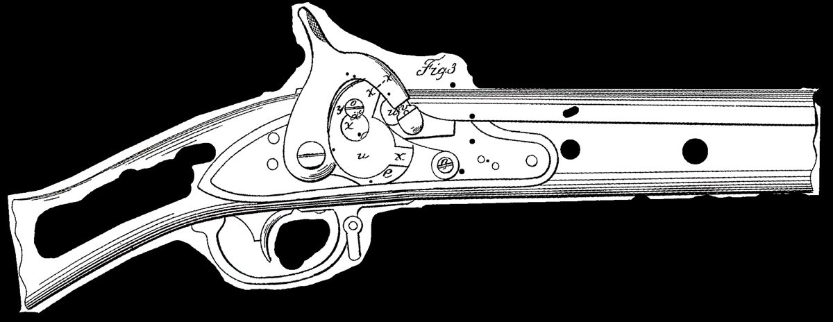
fully represented in the figures. The cavity i, for the reception of the coil of primers, j, has a channel, k, leading therefrom for the delivery of the primers and an enlargement, l, in which turns a feeding wheel, m, with cogs in its periphery so formed and at such distances apart as to fit in the spaces between the primers in the series, which are thus held between this feeding wheel and the under part of the channel, k. This feeding wheel turns on a cylindrical pin projecting from the under plate of the magazine and rests on a spring washer, n, (represented in plan and profile at Fig. 6) which is bent to give it the requisite elasticity, to press the wheel up against the head of a screw, o, that fits accurately in a hole in the cylindrical pin, and tapped into the lower plate. The object of this spring washer is to prevent the return of the wheel by the return action of the mechanism which operates it, and which consists of a hoop spring p, that fits accurately and without much binding in the case or magazine, e. This spring hoop is represented in section at Figs. 11 and 12, the end, q, which acts against the teeth of the feeding wheel is for a short distance tangential to the circle, and that part of the periphery of the magazine corresponding thereto, is of the same form as it will be seen on inspection of the drawings, that if these two parts were in the direction of the circle the end q, in pushing around the feeding wheel would escape from the cog, which is effectually prevented by giving them the direction of a tangent— this is not however indispensably necessary. The mortise in the end, g, shown in Fig. 12, is to receive the tooth of the feeding wheel next to the one acted upon by the end of the hoop spring for the reason given in describing the necessity of making this end tangential. The spring hoop receives the movement which it transmits to the feeding wheel from the cook or hammer by a projection, r, that lies in a mortise, s, in the body of the cock or hammer, as fully shown at Fig. 4 in which a part of the cock is represented as cut off to exhibit this connection. The mortise, s, in the cock is of such length as not to act on the projection, r, in bringing it to the half cock, and then from the half to the full cook, the spring hoop is carried around sufficiently to turn the feeding wheel the distance of one cog, and thus feed out one primer. There is an opening made in the side of the magazine of sufficient length for the play of the projection, r. The outer face, t, of the magazine is a segment of a circle of which the axis of the hammer is the center, and the under and lower faces of the channel k, should be such that the upper part of the strip of primers in being forced out by the feeding wheel will strike the upper face and by its elasticity cause the under side to bear on the lower face, k’, which is made sharp to form a bed cutter, in conjunction with which the knife edge, a, of the hammer acts to constitute shears by which the primer is severed from the strip and carried down by the motion of the hammer to be exploded on the nipple or cone, v, made in the usual form, and which is therefore in a condition to receive the common percussion cap, should it be desired to make use of this as a percussion. cap lock. That portion of the lower face, k’, of the channel on which the strip of primers lies preparatory to being cut off should be so inclined as to deliver the primers in the direction of the dotted line x—x of Fig. 3 or nearly so to insure the carrying of the primer after it is severed from the strip to the cone or nipple. The screw, h, which aids in fastening the magazine to the lock
plate is tapped into a cylindrical projection within the magazine around which the strip of primers is coiled. The magazine is closed by a cap w, hinged at x, and pierced at y, to shut over the head of the screw s, and is latched down by a turning latch plate, z, riveted to the cap, the circle of the latch plate, and that of the screw head intersecting each other, the former being cut out as shown at a’, to pass the head of the screw so that it may be turned into a notch cut in the head of the screw to latch and secure the cap, the latch being provided with a thumb or nail piece by which to turn it. At Fig. 7, will be seen a modification of this magazine separate from the lock to show the mode of feeding without the feeding wheel, by extending the end g, of the hoop spring p, some distance into the channel k, (which is altered in form as represented in the drawing) and so curved as to fit into the recesses between the primers to feed them forward instead of acting on the teeth of the feeding wheel, as in the first example, and to prevent the back movement of the feeding hoop spring from drawing back the primers, they are retained by a spring b’, placed above them and attached to the upper face of the channel, k, and as the screw, o, in this modification is not employed, a projection c’, is substituted to receive the edge of the rotating latch for securing the cap. Another modification is represented in Figs. 8, 9, and 10, in which the magazine is let into the lock plate, and the projection, r, of the hoop spring is embraced and operated by the tumbler, the same amount of play being given to admit of bringing the hammer to the half cock without moving the hoop spring and primer as in the other example. The location of the magazine, hoop spring, feeding wheel, &c., are all indicated in Fig. 9, by dotted lines. From the foregoing the manner of applying the first and second parts, of my invention to cannon, and pistols and other fire arms, and various modifications of locks will be obvious to all persons versed in the art of making fire arms, and it will also be evident that the first part of my invention may be applied without the second, and that the second part or magazine may be applied without connecting it with the lock, and that I have only given the above as examples of what I deem to be the most efficient modes of application; but these may be variously changed without affecting the principle or character of my invention as fully expressed above. And Having thus fully explained the character of my invention, the essential modes of application, and the manner of making and using the same; what I claim as my invention and as distinguished from all other things before known, is— 1. Making primers of fulminating mixtures or such compounds as ignite by percussion in a continuous series, each primer, or any two, or greater number, being separated from the others by a substance which is non- or less combustible than the fulminating mixture by which one or more may be exploded without communicating fire to the others. 2. The mode herein described of moving and measuring out the primers by the movement of the lock, substantially as described. EDWARD MAYNARD. Witnesses: E. OWEN, WM. F. BAYLY.
Maynard first model carbine illustrating the tape primer system. Courtesy Atlanta History Center.
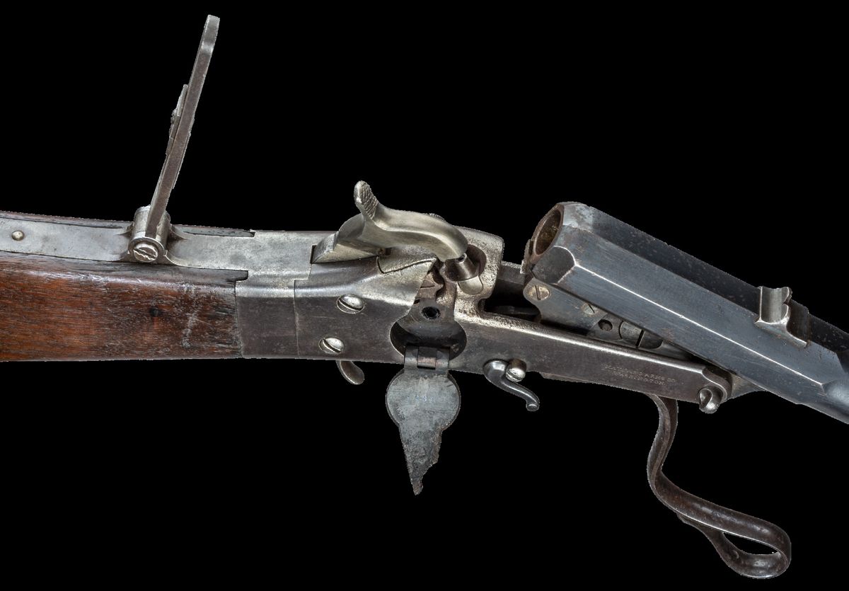
First Model Maynard Carbine The iron toolbox cover has Maynard’s three patents: “MAYNARD PATENTEE / SEP 22. 1845. / MAY 27. 1851 / JUNE 17. 1856.”
SN 4859, .35 caliber. This was a popular military arm in the South at beginning of Civil War, especially in .35 caliber. This gun conforms to other first model carbines, iron mounted, Maynard tape primer system, and a 20-inch barrel. The front sight is missing from dovetailed slot. Note the saddle ring sling swivel.
“MAYNARD ARMS CO. / WASHINGTON.” is stamped on right side of frame. Photos courtesy Poulin Antiques & Auctions, Inc.
This first model has a 3.5-inch adjustable tang sight, and a two position rear sight located on top of the two stage octagonal to round barrel.
Howard Madaus in his article “The Maynard Rifle & Carbine in the Confederate Service” (ASAC Bulletin 52, pages 6679) states that “as many as 2,600 1st Model carbines were purchased by the states of Mississippi, Georgia & Florida.” He also notes that archaeological evidence shows that Maynards issued to Florida troops along the Apalachicola River were using .35 caliber cartridges.
Unidentified soldier in Confederate shell jacket and tricorn hat with first model Maynard carbine. The carbine has the same dovetail front sight, a 2-leaf folding rear sight, and a 3.5-inch adjustable tang sight as shown on the Maynard carbine on the facing page. Liljenquist Family Collection of Civil War Photographs (Library of Congress)
A soldier from a Mississippi cavalry battalion wearing a Confederate wishbone shaped “forked tongue” frame buckle and holding first model Maynard carbine with a military pattern frame that includes a sling ring at the rear of the triggerguard tang. This carbine is like the one on the facing page. Liljenquist Family Collection of Civil War Photographs (Library of Congress)
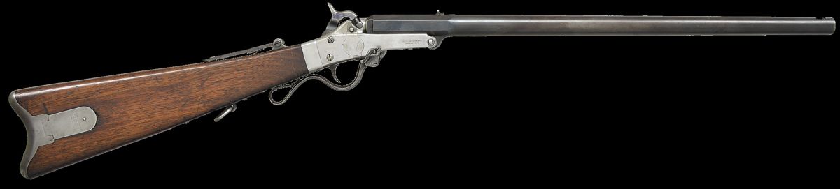
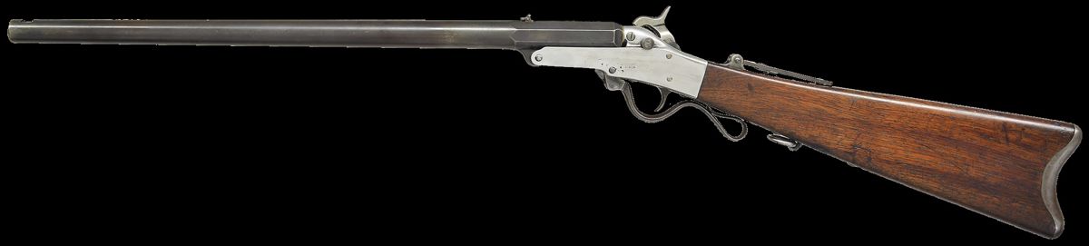
First Model Maynard Rifle
“MAYNARD ARMS CO. / WASHINGTON.” is stamped on right side of frame.
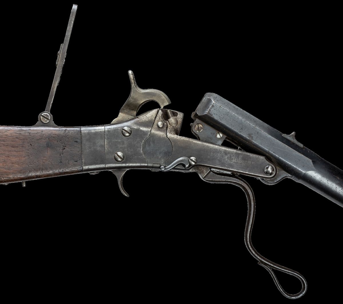
Maynard .50 caliber cartridge. SN 703, .50 caliber with a 26-inch barrel. The first model rifles manufactured with sling swivels found on the 20-inch barrel carbines are rarely seen. Stamped on the left side of frame is “MANUFACTURED BY / MASS ARMS CO / CHICOPEE MASS.” Patch/tool box marked vertically with “MAYNARD PATENTEE” along with three Maynard patent dates. According to Howard Madaus in his ASAC article “The Maynard Rifle & Carbine in the Confederate Service” shows purchases of this weapon by several Confederate states. In the article there is a picture of a Confederate soldier holding an identical rifle. Photos courtesy Poulin Antiques & Auctions, Inc.
from page 5 all Model 1855 .58 caliber military rifles and
carbines made at Federal arsenals. Over 59,000 U.S. M1855 percussion-rifle muskets were produced from 1857–1861. It was the primary arm of the Union at the onset of the Civil War. After receiving the patent for the Tape Primer and Lock System in 1845, and well before his 1854 agreement with Jefferson Davis, Maynard made plans to travel to Europe and Russia to meet with heads of foreign governments in hopes of selling rights to his invention. He left his very successful dental practice in July 1845 and returned in September 1846. He was successful in Denmark, Sweden, France, Belgium, England, Scotland, and Ireland. Russia was a disappointment. After examining Maynard’s invention, the Russian Committee for the Improvement of Small Arms rejected his concept based on “inconveniences of the system.” In a letter home to his wife Maynard suspected that the Russians might well use the invention without purchasing the rights. He related “I am told that no trick or meanness is too low for the Russian Government to practice when either money or power is to be gained, and if this be true I could not reasonably expect to be paid for my invention when it might be used without being paid for by merely violating the law of honor – a law of very little if any consequence dealing with Russians.” Because of numerous delays, the trip that was to last 6 months lasted 15. As a result, Maynard’s funds began to run out. To finance his travel Maynard resumed practicing dentistry. He introduced techniques that were original and innovative. In a time when most dental disease was treated by tooth removal, Maynard was pioneering in restoring and saving teeth. His talents as a dental surgeon were soon recognized. As his reputation grew, so did demand for his services. Ironically, the same Russian leaders who rejected his primer system now sought his dental expertise. Not only was he offered an
Original unopened package of ten cartridges for the .50 caliber Maynard percussion carbine. Package also contains a package of percussion caps in a paper wrapper. Courtesy Union Drummer Boy.
appointment as Dentist to the Court with a high rank of nobility, but overtures were made to him regarding the establishment of a School of Dentistry under his direction. Maynard provided extensive dental care to the Imperial Family of Tsar Nicholas I but declined the offer to become Dentist to the Court. He was well compensated for his expertise, not only monetarily but with gifts as well. On March 10, 1846, Her Imperial Highness Grand Duchess Helen presented him with a thank you gift for services rendered to the Imperial Family. It was a ring consisting of a large red garnet surrounded by 50 small and 16 large diamonds. He considered it a great honor. After a far longer trip than planned, but with the successful sale of firearm ignition licenses to several European markets, Maynard returned to Washington, D.C., in September 1846. He resumed his dental practice and continued his work in Ring given to Maynard. arms innovations. In May 1851 Maynard received a patent for a tipping barrel breechloader. The first model was a carbine that used his Tape Primer System; a second model Maynard Carbine patent was issued in December 1859. The second model used ordinary percussion caps. Pulling down the carbine’s trigger guard unlocked the barrel and opened the breech for loading. Both types of carbines were manufactured in .35 and .50 caliber models. The second .50 caliber model was produced in much greater numbers than the first model for military purposes. Maynard also offered sporting rifle models in .35, .40 and .50 calibers and a .64 caliber shotgun. The barrels were interchangeable.
Percussion caps for Maynard firearms.
In April 1857 Maynard and several investors formed the Maynard Arms Company of Washington, D.C. They contracted all its manufacturing with the Massachusetts Arms Co. of Chicopee Falls, Mass. In June 1856 Maynard received the first of several patents for a metallic cartridge designed to be used with the Maynard carbine. It was a cylindrical brass shell with a wide rim at its base. The rim had a centrally located hole that allowed the flame from the primer, either Maynard’s tape or a percussion cap, to ignite the cartridge powder charge. The metal cartridge increased accuracy, durability, and speed of loading. The brass shell could be reloaded dozens of times. Eventually the U.S. government adopted the concept for all breech loading arms. The metal cartridge would become the standard cartridge for rifles worldwide.
Maynard made his own dental instruments. Among them was the Barbed Broach for use in root canal therapy. The Barbed Broach was used to remove diseased neuro-vascular tissue in tooth root canals. It also widened the canals so they could be filled with an inert material such as gold foil. Modern versions of the Barbed Broach still find applications today in root canal procedures. Maynard pioneered in restorative techniques to
All Maynard’s accomplishments prompted Abraham Lincoln, a personal friend, to comment “Dr. Maynard you have increased the entire army without adding a single man to the ranks.”
Barbed broaches pioneered by Maynard for root canal procedures.
By 1862 the manufacture of the Tape Primer System came to a close. It was found that it did not perform well in inclement weather. That contradicted the findings of the 1845 tests: during those trials water was poured over the lock and into the magazine. Although some misfires occurred, the system still performed extremely well. Maynard attributed the misfires to defects in the tape’s waterproofing. Most likely as the tapes aged and were handled in rugged field conditions, the varnished covered paper tape developed imperfections. There were other problems as well. The pawl that advanced the tape often detonated the primer when it was pushed into the exit slot before it got to the cone. At other times, the primer correctly sat on the cone but did not detonate.
maintain good oral health. While Maynard was mostly known for his achievements in the fields of firearms and dentistry, he was also an artist, architect, wood engraver, surveyor, and a true renaissance man. Maynard passed away at age 78 on May 4, 1891. He is buried in the family plot at the Congressional Cemetery in Washington, D.C. References Edwards, William B., Civil War Guns, Castle, 1982. Glenner, Richard A., The American Dentist, Pictorial Histories Publishing Co., 1990. Gluckman, Arcadi, United States Muskets, Rifles and Carbines, The Stackpole Co., 1959. Hatch III, Rodney S., Dr. Edward Maynard, “Letters from the Land of the Tsar 1845–1846”, America’s Pioneering Dental Surgeon Turned Civil War Gun Inventor, Iron Horse Publishing, 2010. Koch, Charles R.E., History of Dental Surgery, National Art Publishing Co., 1909. Silha, Robert E., Dental Radiography and Photography, Eastman Kodak Co., Vol. 39, No. 4, 1966. Madaus, Howard Michael, “The Maynard Rifle and Carbine in the Confederate Service,” American Society of Arms Collectors Bulletin, No. 52, April 1985, pp. 66-79. https://americansocietyofarmscollectors. org/wp-content/uploads/2019/06/1985-B52-The-Maynard-Rifle-andCarbine-in-the-Con.pdf.
In 1856 Maynard was appointed Chair of Theory and Practice of Dental Surgery at the Baltimore College of Dental Surgery. He also held a similar position on the dental faculty of the National University of Washington. As a researcher he made important discoveries in dental anatomy and the anatomy of the maxillary sinuses. His work with microscopic analysis of dental hard tissue resulted in techniques that considerably lessened the discomfort of tooth restoration. He discovered a great diversity of form, shape, and capacity of the maxillary sinuses. This was considered of great importance when treating diseases of the sinuses.
About the Author
Peter H. Jacobsohn, DDS, is retired from the practice of Oral and Maxillofacial Surgery and from the Chair of the Division of Oral and Maxillofacial Surgery of Marquette University School of Dentistry in Milwaukee, WI. He is a past-president of the American Academy of the History of Dentistry and the Civil War Round Table of Milwaukee. Currently he is curator of the Dental Museum of Marquette University. He writes and speaks on various topics related to the history of dentistry and medicine as well as aspects of the Civil War, World War I and II.
Peter H. Jacobsohn, DDS
Overall obverse view of the 1847 Rifled and Sighted cavalry carbine. All photographs by Tim Prince.
Close up of lock with SPRING / FIELD / 1848, eagle / U S.
Close up of the script JS cartouche of Springfield Arsenal’s James Stillman.